Installing a performance clutch is about far more than simply bolting it to the flywheel and connecting the hydraulics.
When it comes to a custom UniClutch installation, getting the measurements, clearances, release-bearing position and hydraulic stroke correct is critical. A clutch that is incorrectly spaced or over-stroked can drag, make it difficult to select gears, lose clamping force or, in the worst case, destroy itself.
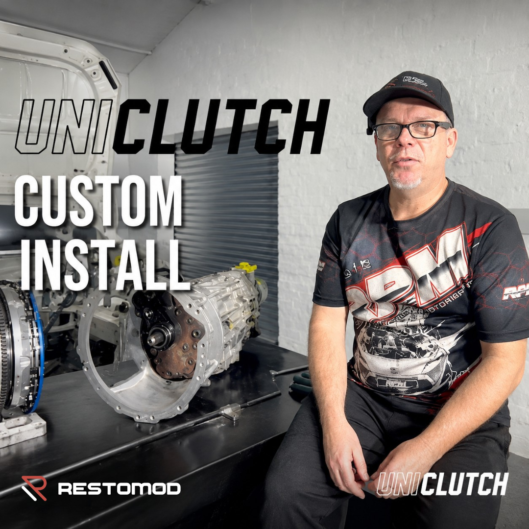
Mark from RPM recently walked through a fully custom UniClutch installation, including a custom bellhousing, flywheel and hydraulic cylinder setup, explaining the checks that should be carried out before the vehicle is driven.
Here are the key measurements and procedures every installer should understand.
Start With Accurate Measuring Equipment
The first requirement is accurate measurement.
For basic setup work, an electronic vernier and a known-straight straight edge are invaluable. By placing the vernier against the straight edge and zeroing it, the thickness of the straight edge is automatically accounted for, allowing you to measure directly from the reference surface to the component.
This is particularly important when working with clutch dimensions.
A tape measure simply isn’t accurate enough for this type of work. Being out by only a couple of millimetres can significantly affect clutch operation and, depending on the setup, potentially cause damage.
Check the Gearbox Spline First
Before worrying about release-bearing position or hydraulic stroke, the first thing to establish is that the clutch spline is correct for the gearbox.
Once the clutch has been selected, check that the spline properly matches the gearbox input shaft.
The clutch then needs to be positioned so that the spline fully engages with the input shaft without creating interference elsewhere.
This is particularly important on custom installations where the bellhousing, flywheel and clutch combination may not have been designed as an original factory package.
The distance from the bellhousing face to the point where the clutch spline is fully located on the gearbox input shaft establishes an important reference dimension.
Once that position has been established, there is typically some adjustment available within the installation range, but you must also ensure that the clutch, release bearing and surrounding components have adequate clearance.
Measuring the Clutch Casing Height
With the flywheel installed, the next step is to establish the clutch casing height relative to the bellhousing face.
In the example demonstrated by RPM, the measurement from the bellhousing face to the clutch casing was 106 mm.
The important point is not simply the number itself. It is establishing an accurate, repeatable reference dimension from which the rest of the clutch setup can be calculated.
Once the casing position is known and the spline is correctly located, you can begin working towards the release-bearing and finger-height measurements.
Understanding Finger Height
Finger height is another critical measurement.
In the example installation, the clutch casing measurement was 106 mm and the relevant finger dimension was 8.5 mm.
That produced a finger height of:
106 mm − 8.5 mm = 98 mm
This 98 mm dimension becomes the reference point for determining where the release bearing needs to sit and how much preload or free play is required.
Getting this relationship wrong can result in a clutch that either doesn’t fully release or is permanently partially activated.
Choosing the Correct Release Bearing
The release bearing is another component that deserves attention.
For the UniClutch application demonstrated, a flat-face release bearing is recommended rather than a stepped bearing.
The bearing needs to contact the clutch fingers correctly without catching on or interfering with them as the clutch is activated.
The diameter is also important. UniClutch provides minimum and maximum bearing diameter specifications for its clutch assemblies.
The example bearing measured approximately 54 mm and provided good contact with the fingers.
There is also a relationship between bearing diameter and pedal effort. Moving the contact point further towards the centre of the clutch fingers generally reduces the effort required to activate the clutch, while a larger contact diameter can increase the required effort.
Always Check Clutch Runout
Runout is another measurement that should never be overlooked, particularly with twin-plate or other multi-component clutch assemblies.
A dial gauge should be used to check both axial and radial runout.
For the UniClutch setup demonstrated, the maximum specified runout was:
0.15 mm axial and radial
Excessive runout can contribute to clutch noise and may place additional stress on components such as the internal damper.
This is a relatively simple check, but one that can prevent significant problems later.
Hydraulic Stroke Is Critical
Once the mechanical dimensions are established, attention turns to the hydraulic system.
The slave-cylinder size and master-cylinder combination determine how much movement the release bearing receives.
For the UniClutch system demonstrated:
* 6.5 mm: clutch begins releasing * 8.5 mm: full release * 11 mm: maximum recommended finger travel
That 11 mm maximum is particularly important.
Going beyond the specified travel can over-stroke the clutch. This can make gear selection difficult and can also reduce the clutch’s clamping capability by effectively over-bending the diaphragm fingers.
More hydraulic travel isn’t necessarily better.
The objective is to achieve enough movement to completely release the clutch, while staying comfortably below the maximum permitted stroke.
Why Slave-Cylinder Size Matters
The installation demonstrated how changing the slave-cylinder size can dramatically affect clutch travel.
The original cylinder produced approximately 8 mm of release-bearing movement. That was marginal because the clutch requires approximately 8.5 mm for full release.
The cylinder was therefore changed to a larger ¾-inch-bore (approximately 19 mm) unit, which produced approximately 9.5 mm of travel.
That provided enough movement for complete clutch release while remaining below the 11 mm maximum.
This is a good example of why hydraulic components cannot simply be selected independently. Master-cylinder size, slave-cylinder size, pedal ratio and clutch requirements all need to work together.
Free Play: The Measurement That Can Save Your Clutch
Even if the clutch reaches full release, the installation isn’t finished.
Free play is critical.
As a clutch wears, the diaphragm fingers move progressively outward towards the release bearing. The release bearing therefore needs sufficient clearance to move with the changing position of the fingers without permanently loading them.
If there isn’t enough free play, the release bearing can remain in contact with the fingers and effectively keep the clutch partially activated.
It’s similar to driving with your foot resting on the clutch pedal.
The result can be rapid clutch wear and eventual failure.
For the installation demonstrated, the target was approximately 6–8 mm of free play, with the measured setup producing 7 mm.
That was considered ideal for the application.
A Simple Way to Check Clutch Operation
One useful practical check is to install the prop shaft or gearbox yoke and verify that the gearbox is engaged.
With the clutch released, the prop shaft should be locked because the clutch is transmitting drive through the gearbox.
When the clutch pedal is depressed and the clutch reaches full release, the prop shaft should be able to rotate.
As the pedal is slowly released, the clutch should begin to grab at an appropriate point in the pedal travel.
The installation demonstrated a target of approximately one-quarter of the pedal travel from the bottom for the clutch to begin engaging, with the clutch fully engaged around the halfway point.
The exact pedal feel will depend on the vehicle and hydraulic system, but the principle is important.
If the clutch only starts grabbing right at the top of the pedal, something in the setup may be incorrect — potentially the clutch spacing or hydraulic stroke.
If it grabs immediately as the pedal begins coming off the floor, the clutch may be dragging and may not be fully releasing when the pedal is depressed.
That can result in difficulty selecting gears, particularly first and reverse, and can cause gear grinding.
Preventing Clutch Over-Stroke
In some applications, the hydraulic system can produce more travel than the clutch requires.
For example, a change to a smaller slave cylinder can increase release-bearing travel. While this can solve a clutch that isn’t releasing fully, it can also create a situation where the clutch is being over-stroked.
If the maximum permitted movement is 11 mm and the hydraulic system can produce 14 mm, the system needs a mechanical limit.
This is where a pedal stop becomes important.
The clutch should be measured to determine exactly where maximum permitted finger travel is reached, and the pedal stop should then prevent the pedal from travelling beyond that point.
This is common practice in race and competition vehicles where precise clutch travel is required.
Pedal Pressure Is Another Useful Measurement
The final check demonstrated by RPM was clutch pedal pressure.
The twin-plate UniClutch installation required approximately 12.8 kg of foot pressure to activate the clutch.
For comparison, a standard Toyota Hilux clutch was quoted at approximately 16 kg.
That means the performance twin-plate setup in this particular application actually required less pedal effort than the standard Hilux clutch.
Pedal pressure will vary depending on the clutch design, diaphragm characteristics, hydraulic system, pedal ratio and release-bearing position, so this isn’t a universal comparison between every UniClutch and every factory clutch.
Don’t Assume a Standard Vehicle Doesn’t Need Checking
These checks aren’t only relevant to highly modified cars.
Even on a standard vehicle with a standard flywheel and clutch, it is good practice to verify the critical dimensions when replacing components.
Flywheels can be changed, machining can alter dimensions, hydraulic components can be replaced, and previous repairs may have introduced changes that aren’t immediately obvious.
If a vehicle is repeatedly destroying clutches or experiencing clutch-release problems, assuming the clutch itself is at fault isn’t always the answer.
The problem could be incorrect spacing, insufficient free play, inadequate hydraulic travel, excessive travel, incorrect release-bearing geometry or excessive runout.
The Bottom Line
A performance clutch installation is a system, not simply a collection of parts.
The clutch, flywheel, bellhousing, gearbox input shaft, release bearing, master cylinder, slave cylinder and pedal mechanism all need to work together within the manufacturer’s specifications.
The key checks are straightforward:
Measure accurately. Check spline engagement. Confirm clutch spacing. Calculate finger height. Use the correct release bearing. Check runout. Confirm hydraulic travel. Set the correct free play. Check where the clutch engages. Prevent over-stroking.
Taking the time to make these measurements before driving the vehicle can save a considerable amount of time and money — and potentially prevent an expensive clutch failure.
For anyone fitting a UniClutch to a custom application, the manufacturer’s specific installation instructions and specifications should always take priority over general guidelines.
Technical information and installation demonstration: RPM.